50MHz FM Hospital Radio Link
Edinburgh Hospital Broadcasting Service (EHBS) covers a number of
Edinburgh Hospital's from one Studio. The service used to be fed to remote Hospital's
via leased analogue telephone lines, the digital age however, brings an increasing reluctance for BT to provide this facility.
As well as disrupting service this also limits the possibilities for outside broadcast's, used to generate funds for
the charity. Several radio frequencies have been made available for use as 'Land Line
Replacements', EHBS holds licences for two frequencies, 48.425MHz and 52.875MHz.
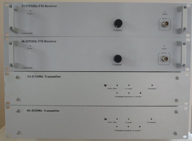
There is a limited range of equipment available for these frequencies and
what is available is very expensive. Over a number of years the Transmitter/Receiver pairs
shown here were developed for the purpose.
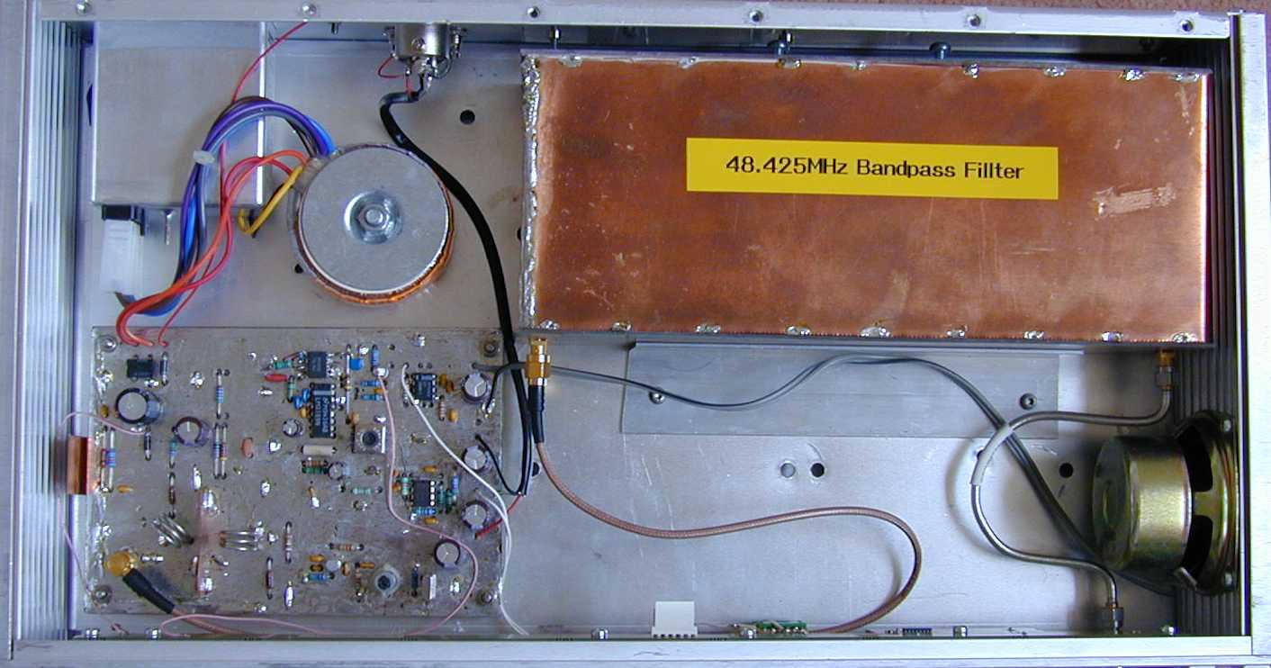
The receiver shown above was developed around the LM3189 receiver IC. An input
filter, low noise front end, fixed crystal LO and an IF consisting of two 130kHz wide ceramic
filters completes the architecture. Audio output is 775mVRMS balanced into 600R.
In the outside broadcast mode the link is by-directional, this means that each
sensitive receiver (-110dBm or 10 pico Watts!) will have a ~5 Watt transmitter (+37dBm) physically
nearbye and only 4.45MHz away in frequency. This calls for a very sharp filter on the input of
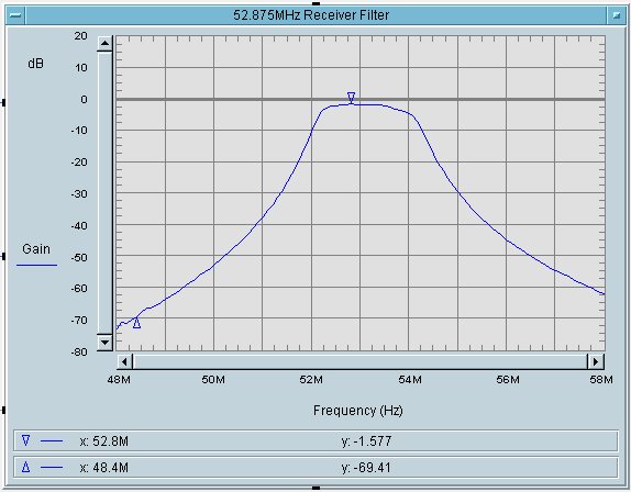
the receiver. The large filter seen in the receiver is a 4 resonator Helical filter designed to
give low insertion loss and 70dB rejection of the unwanted frequency. The filter was constructed
using 40mm plastic waste pipe for the resonator formers, the cavities are made up of PCB material
and copper sheet soldered together. The response of the completed filter is shown above. The use
of this type of filter along with the two ceramic filters at the IF, allow the receiver's to be oblivious
to their noisy neighbours.

The transmitter is PLL controlled and uses a crystal reference at 1/10th the RF
frequency. The main RF sections are housed in 3 seperate dicast boxes to give the best isolation.
The first box (left) contains the frequency reference/dividers and the phase detector.
The second box contains the loop amplifier with 20Hz bandwidth, audio input section, lock detector,
discrete VCO and buffer amplifiers. There is also dedicated power regulation for the VCO. The third box contains
a driver amplifier for the PA. On the output of the driver there is a band pass filter to limit the broad
band noise transmitted, this would affect the sensitivity of nearbye receiver's, including our own.
The PA is a 'Hand's Electronics' kit giving in excess of 5 Watts output, the output is via a 7th
order low pass filter to kill harmonic's and possible interference to other equipment. The audio
to the modulator is supplied via a limiter/compressor which keeps the transmitter deviation
within the 50kHz spec. This circuitry was a kit from
Veronica. Prior to the limiter there
is a differential to single ended amplifier board.
The enclosure's for this equipment were sourced from scrap test equipment.
The larger transmitter case came with the advantage of a fan and power supply which were adapted to suit.
The licence calls for directional antenna's to be used and to this end two 3 element
Yagi's were constructed for the transmitters, the receivers used dipole's. The Yagi's were developed by scaling
a 50MHz amateur band design.