Solar Power Supply
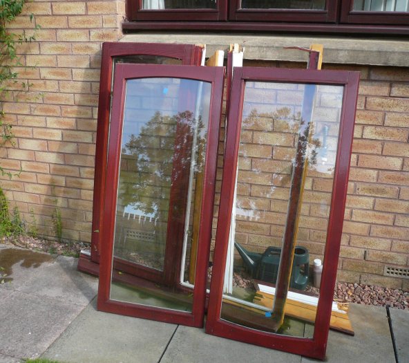
I was replacing some windows in my house and had the idea that the old double glazed units
could be used to make some solar panels. The double glazed units were removed from the wooden frames and the silicone holding the
two sheets of glass to the spacer bar was cut away. I then removed one sheet of glass, this left me with a base sheet of glass and
spacer bar to work with as my substrate.
I had a rummage around the internet looking for the individual cells and ideas of what had been done before.
It seems that there is quite a lot of activity in this area. I guess this is due to the increase in popularity in commercial solar units.
The cells themselves are extremenly brittle and there seems to be a decent market selling the broken cells. Standard cells
are 6*6 inches and the broken portions are lazer cut off to give a 3*6 inch cell. There are various grades of these available
depending on cosmetic condition. The cells shown below were bought from Ebay for 65pounds.
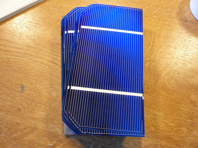
These cells are the Monocrystalline veriety which give the highest efficiency.
Polycrystalline dont give the same output but appear to be more readily available since they are cheaper to make. Each Monocrystalene cell
is specified to give 0.62v and 3.8A peak in bright light.
36 of these cells are generally wired in series to give 18v nominal - enough to charge a 12v lead acid battery.
My windows were only big enough to allow me to use 35 cells but given that I was using the more efficient cells I suspected
I would get away with loosing one cell.
The first panel I built is shown below. This was one of the most tedious frustrating projects I have taken on,
you only have to look at one of these cells the wrong way for it to shatter into pices.
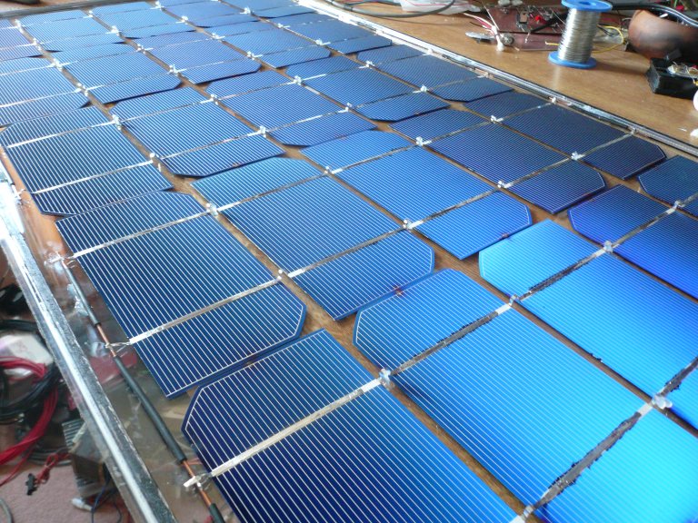
Between each cell I have a little stress relief wire loop to allow movemet due to temperature etc
without the cells shattering. The cells are secured to the glass substrate using a blob of glazing silicone on these loops.
The second panel was much easier to do since I had figured out the best techniques for soldering and securing the cells.
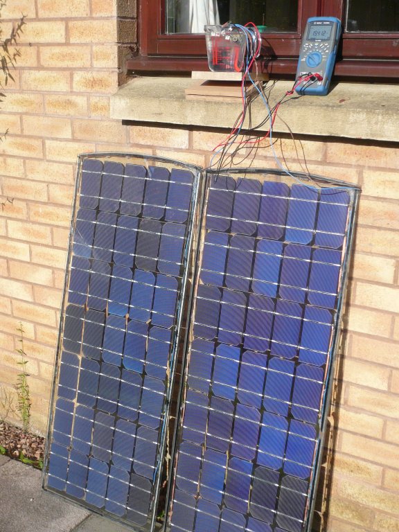
The picture below shows the first test I made with two panels. With some late summer sun I'm getting 15.5v across
2.2ohms. This amounts to 110W which is why the resistors are dunked in a jug of water! I'm quite happy with this 110W
since the load impedance is not optimized for maximum power at this stage.
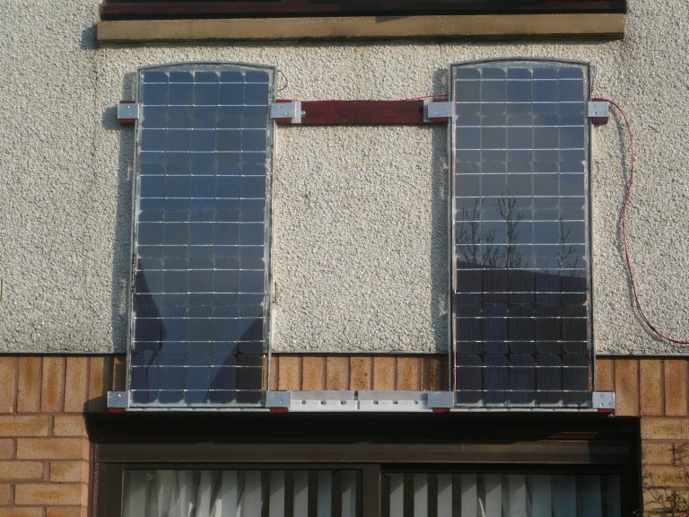
The picture below shows the panels fixed to the south side of my house. There is space for the third panel to be added
at a later date if I decide this is needed. They would of course be better fixed to the roof but I dont have a long enough ladder
and Im not really keen on messing around with the tiles - maybe at a later date.
The plan was to use the panels to charge a lead acid battery during the day, this will then be used to power a mains inverter
at night. There should be enough power available to power my TV and table lamp. In the summer time I would also hope to power my laptop and
modem during the day.
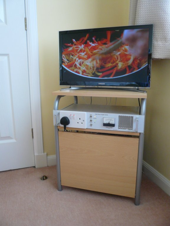
The picture below shows the main box of tricks. This makes use of the enclosure from scrap test equipment.
The charge controller is in the centre. This is basically a couple of comparitors and an SR flip flop. The comparitors monitor
the battery voltage, charging is initiated at 12.6v and teminated at 14.4v. The circuitry is also reset as the voltage from the
solar panel drops overnight. This means that each day starts with a charge cycle whether the battery needs it nor not.
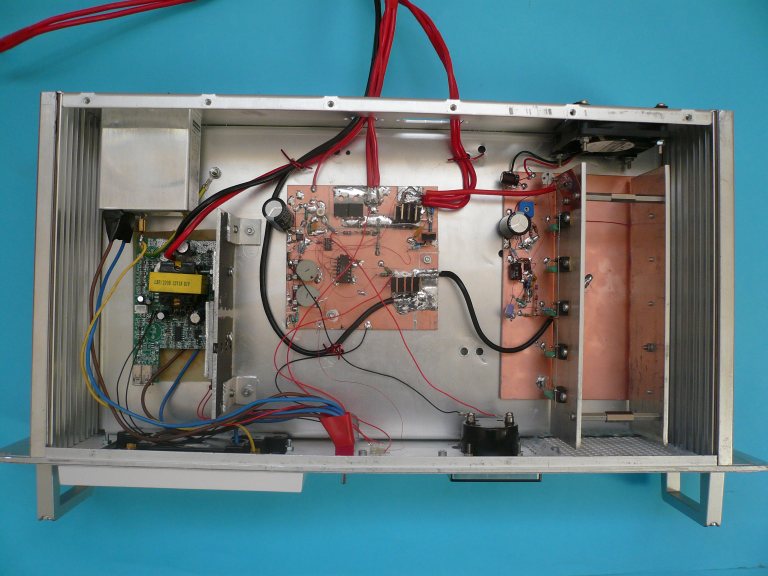
On sunny days it does not take long for the battery to charge and afterwards it would seem shamefull not to use
the available power. To the right hand side of the unit there is an electronic load which dissipates as much power as the panels
will provide. This basically acts as a small heater. There is a fan at the back and the speed of this is modulated by the current
through the load. This load can be switched off in the summer time when I dont want any power being dumped into the room and also
when I expect to be powering other things during the day.
The mains inverter is on the left. This is the circuirty from a cheap module bought on Ebay. Its spec'd at 200W
and the output is described as a modified sine wave. Its essentially a square wave with a large dead time resulting in a 3 state waveform.
The whole system is shown in operation below.